| Products | Events | Support | Company | Contact |
| Products |
 Caspoc Caspoc |
 Tesla Tesla |
 What is Tesla What is Tesla |
 Features Features |
 Machine Types Machine Types |
 Read more Read more |
 Euler Euler |
 Integrated FEM/BEM Integrated FEM/BEM |
 Services Services |

FreeWare/Viewer
Download here!


for
Education!
Please visit our new site
www.caspoc.com
Rapid Application Development Tool Tesla for Fast Prototyping of Electrical Machines
Peter van Duijsen
Davor Gospodaric
Abstract
Designers of electrical machines and drives need a Rapid Application Development (RAD) tool during the design phase of an electrical machine in order to perform fast prototyping. Using the tool various prototypes of machines can be designed.
I Introduction
In this paper a Rapid Application Development tool is described for fast prototyping of Induction, DC, Permanent Magnet, Universal, Synchronous and BLDC Machines. Using the tool the designer can enter geometric data, material data and mechanical data, and obtain the performance of the machine such as speed-power, speed-efficiency, and speed-torque characteristics.
Also simulation models are generated for testing the prototype in a system simulator, where it is connected to the power electronics, driving mechanics and the control of the drive.

Figure 1: Coupling between the design tool and simulators
Coupling to FEM/BEM tools is provided for a more detailed design of the machine where a magnetic, thermal and mechanical strength analysis can be performed. Optimization can be performed on the design of the machine or on the overall design of the drive system, where the machine is one of the components.
The tool is based on the idea of a construction kit where basic designs of typical parts, such as rotor, fan, windings, magnetic material, bearings, rotor bars, etc, can be constructed that are manufacturer specific. Using such libraries of components, the user can prototype various variants of his design based on standard parts already designed.
The calculation of the characteristics is done using analytical methods and dedicated numerical routines inside the Rapid Application Development tool and therefore the response to the user to a change in parameter is interactive. In the tool the complete magnetic circuit is analyzed, resulting in the characteristics of the machine. Here the non-linear material characteristics are used for the applied magnetic materials. Wire parameters are based on standards such as DIN, SEV, JASO, etc. For the geometric data the designer can mix SI and US metrics such as "inch" and "mm" in one design and couplings exists to popular CAD packages.
Compared to lengthy Finite Element simulations the user is able to prototype a new type of electrical machine in a very fast way.
II Basic Modules
The basic modules in the Tesla suite of design tools are broken down into six specific modules for various types of motors.
TESLA-A
Calculates the operational characteristics of 3-phase induction motors. The software utilizes classical numerical theory for solving induction machines.
TESLA-G
Offers the possibility of practice-oriented calculations of D.C commutator motors. TESLA-G is used to model:
- Shunt connected commutator motors (self-excited)
- Shunt connected commutator motors (separately excited)
- Series motors
- D.C motor with compound excitation
TESLA-P
Calculates permanent magnet D.C motors. TESLA-P considers the numerical possibilities of the iterative treatment of non-linearity and the effect of magnetic field calculation. The program takes into account the effects of demagnetization and temperature distribution.
TESLA-S
Calculates the operational characteristics of synchronous motors.
TESLA-U
Calculates universal series motors.
TESLA-E
Calculates brushless D.C. motors. TESLA-E solves both 2 phase and 3 phase brushless D.C. motors with both slotless and slotted stator windings.
III. Requirements of the design tool
A design tool for electrical machine would need the following features:
- Direct interface to external field calculation software, such as Ansys[6], DynaCom[1], Amperes[8] and Magneto[8] and simulation tools like Spice, Simulink and CASPOC[9]
- Library of pre-calculated flux curves
- Motor component library for easily designing stators, rotors and commutators
- Non-linear analysis capabilities
- Calculation of mechanical and electrical losses due to air friction, bearing loss, blower/fan loss, copper loss, hysteresis loss and eddy current loss
- Outputs such as power, currents, efficiency, lamination data and dimensioning, speed/torque curve, etc
- Graphical outputs such as lamination geometry, magnetization curves, current, efficiency, speed, torque, power and power losses
- Archiving capabilities of all motors and motor components allowing for search capabilities on past motor designs.
IV Coupling
The design tool should have the possibility to couple directly with CAD and Simulation packages.
In the first place the prototype is build from a basic geometry. From these data a 2D or 3D

Figure 2: Generator simulation with stator design template
CAD model can be exported for further mechanical and electromagnetic design.
In many cases a rotational 2D model would be satisfactory. Also material data for the properties of the non-linear material has to be supplied to the CAD package. For 3D modeling in CAD packages the export of the lengths and an eventual rotor skewing has to be done.
In the second place the prototype has to be tested in a complete drive simulation. Therefore the electromagnetic model has to be exported into a behavioral model required for simulation. Not only should the model and the parameters contain the electrical parameters, but also the mechanical parameters are required for the simulation, such as the rotor inertia and friction of the bearings.
Since the prototyping takes place in the design tool and because of its connections to the system simulation, optimization can be performed based on the prototype of the machine inside the complete drive, including the power converter, mechanical load and control circuitry or embedded control.
Figure 2 shows the simulation of a synchronous generator with rectifier and buck converter. The design of the generator is carried out in the RAD tool Tesla. The parameters of the behavioral model of the generator are used for the model in Caspoc.
The templates for the machine are selected from the project manager in the design tool. For each component a template exists that guides the designer to enter specific values for the design of that particular component.
More components can be defined and stored in a project. For example, 3 different types of stators can be defined and each of them can be used in the total design.
The parameters for the prototype are automatically transferred to the simulation tools, so changes in the design are immediately effective in the simulation. This allows fast prototyping of not only the machine but also performance of the machine in the total drive system.

Figure 3: Design Process
V Machine EM design
The electrical machine is mainly designed for the electromagnetic properties. In figure 3 the process from geometric data to design info is shown.
The input for the design is not only geometrical data, but also material data has to be supplied
Important are the non-linear materials, see figure 4.

Figure 4: Non-linear material properties
Manufacturers provide libraries with data for their materials, such as, for example, iron and magnetic materials. From this data losses such as hysteresis and eddy current losses are calculated.
The data for the windings allows copper losses to be calculated.
In the design tool the behavior of the machine is calculated directly using analytical expressions. This allows the fast determination of specific design considerations, such as power and speed curves. Also, for example, the efficiency as function of the speed of the rotor can be displayed graphically. From these data the machine can be optimized.
Figure 5 shows the analytical results from Tesla. Shown are the efficiency (*10%), power (*1000 w), current (*100 A) and speed (*1000 rpm) as function of the torque (Nm)
The parameters for the behavioral model in Caspoc are exported in a model file. For example, parameters for a Switched Reluctance Machine are exported as:
.model srm68_1 user
br=0.436 bs=0.349
lmax=110m lmin=10m
nr=6 ns=8 r=50 jr=10m

Figure 5: Graphical results from Tesla
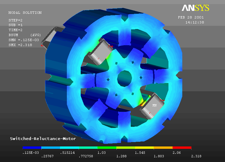
For a more detailed analysis of the electrical machine the prototyped design can be exported into a FEM/BEM package. Since all geometric data is entered in the design tool, the model is exported automatically to the FEM/BEM package Only data such as the length of the rotor and rotor skewing has to be provided in addition to a rotational symmetrical 2D model. Figure 7 shows the model of a Switched Reluctance Machine in Ansys.
Also mechanical components are prototyped in the design tool. In figure 6 the template for a fan is shown.

Figure 6: Prototyping of mechanical components

Figure 7: Model of a Switched Reluctance Machine in a FEM package
Summary
A new Rapid Application Development tool is presented for fast prototyping of electrical machines. Models from the prototype can be used in CAD-, Finite Element and Simulation software. The electromechanical characteristics are obtained using the RAD tool and enable the designer to optimize the design in a short time and very cost efficient.
Literature
- Gospodaric D., Schmenkel A., Simulation of Power Trains for Hybrids and Electrical Cars, Proceedings PEMC Cavtat 2002
- Duijsen. P.J. van, Simulation and animation of power electronics and electrical drives, PCIM Europe, December 2001, p 26-28. www.caspoc.com
- Otto J., Killat U. van Duijsen P.J., Energy Based Model Synthesis for Electrical Actuators and Sensors, PCIM, Conference proceedings IM, 2002, Nürnberg, Germany 2002
- Killat U., Otto J., van Duijsen P.J., Parameter extraction in FEM models for dynamic system simulations. PCIM, Conference proceedings IM, 2002, Nürnberg, Germany 2002
- Matveev A., van Duijsen P.J., Novel Caspoc-based software for multilevel simulation of switched reluctance drives. Proceedings PCIM 2003
- ANSYS Theory Manual, Release 5.7, Swanson Analysis Systems, Inc., 2001
- Simulation Research / Trimerics, Tesla users manual 2003,
- IES Amperes / Magneto, Users manual 2003
- Simulation Research, Caspoc Users manual, 2003,